
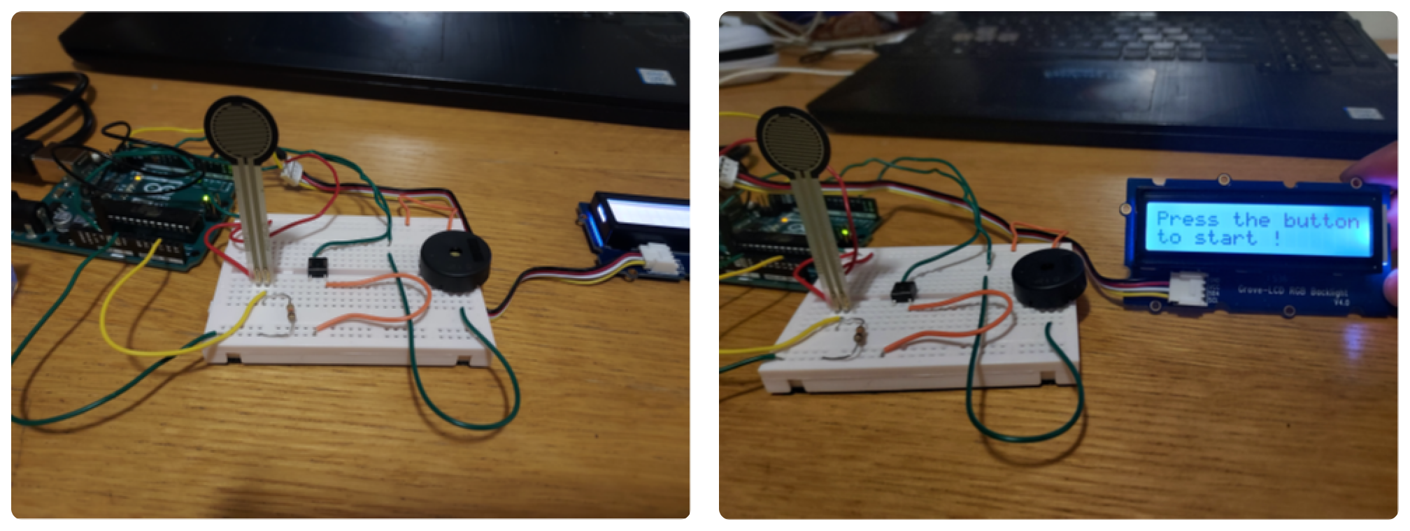
The project commenced with me exploring the possibilities of using an Arduino Uno R3 with a Velleman VMA01RGB LED shield. With the help of my batchmate who had previously worked on a similar project I familiarized myself with the various functions that can be used to operate the Arduino. After spending a significant amount of time with the LCD and the Arduino, I began to investigate potential projects that could improve my technical skills and understanding of digital games.
Digital games refer to any game played using electronic devices, whether online or standalone. The player's interaction with the electronic system affects the display. I studied the different types of games and their evolution in terms of how they are played. Research has shown that digital games can support cognitive skills, pattern recognition, conceptual understanding, attitudes, identity, and engagement. Numerous studies have acknowledged the potential of games as a systematic learning tool.
During my research, I discovered the psychology behind the popularity of retro gaming, which primarily stems from nostalgia. According to Soho MD cofounder Jacques Jospritre Jr., retro game shave intrinsic and extrinsic properties that explain their popularity. The intrinsic aspect relates to the classic gameplay experience, while the extrinsic aspect involves positive associations with people, places, and other factors. The combination of these factors drives renewed interest in this genre. Feldmeier claims that nostalgia plays a crucial role in emotional resilience, and reminiscing about happier times can provide hope for the future.
Based on my findings, I decided to create a retro mini gaming console with interactive features for playing simple retro games that can be enjoyed by both the elderly and children. The interactions required to play the game will be unique and challenge traditional styles of play. This product can serve as a casual icebreaker during intense gaming sessions and add aesthetic value to your gaming setup. I also decided to use Fusion360 as it gave me the features of Designing, Modelling, Rendering, Animating, and creating Technical Drawings all in one software.
To begin my design process, I first began by creating mood boards of current gaming console I was inspired by. I did this to gain inspiration for my design and research what is currently in the console market. I researched many different consoles of different shapes, forms, and colours, that all have different functions and purposes.

First, I started sketching designs for my console. I wanted to experiment with various body shapes and sizes while keeping ergonomics in mind. So, I tried out different thicknesses, lengths, curves, fillets, and chamfers to explore all the possible options.

After sketching out all my ideas, I began to narrow them down to my favourites. I selected a suitable design that met my intended function and began to further develop it. I experimented with different ways to enclose the LCD display, the beeper, the push button, and the switch within my chosen design. I also tried out various methods for closing the body of the console. I will discuss these details more in-depth during the creation process. Additionally, I planned out the necessary measurements for the design, considering the required width and length of each piece. Overall, I put a lot of thought and effort into the design process to ensure that the final product would meet my desired specifications.

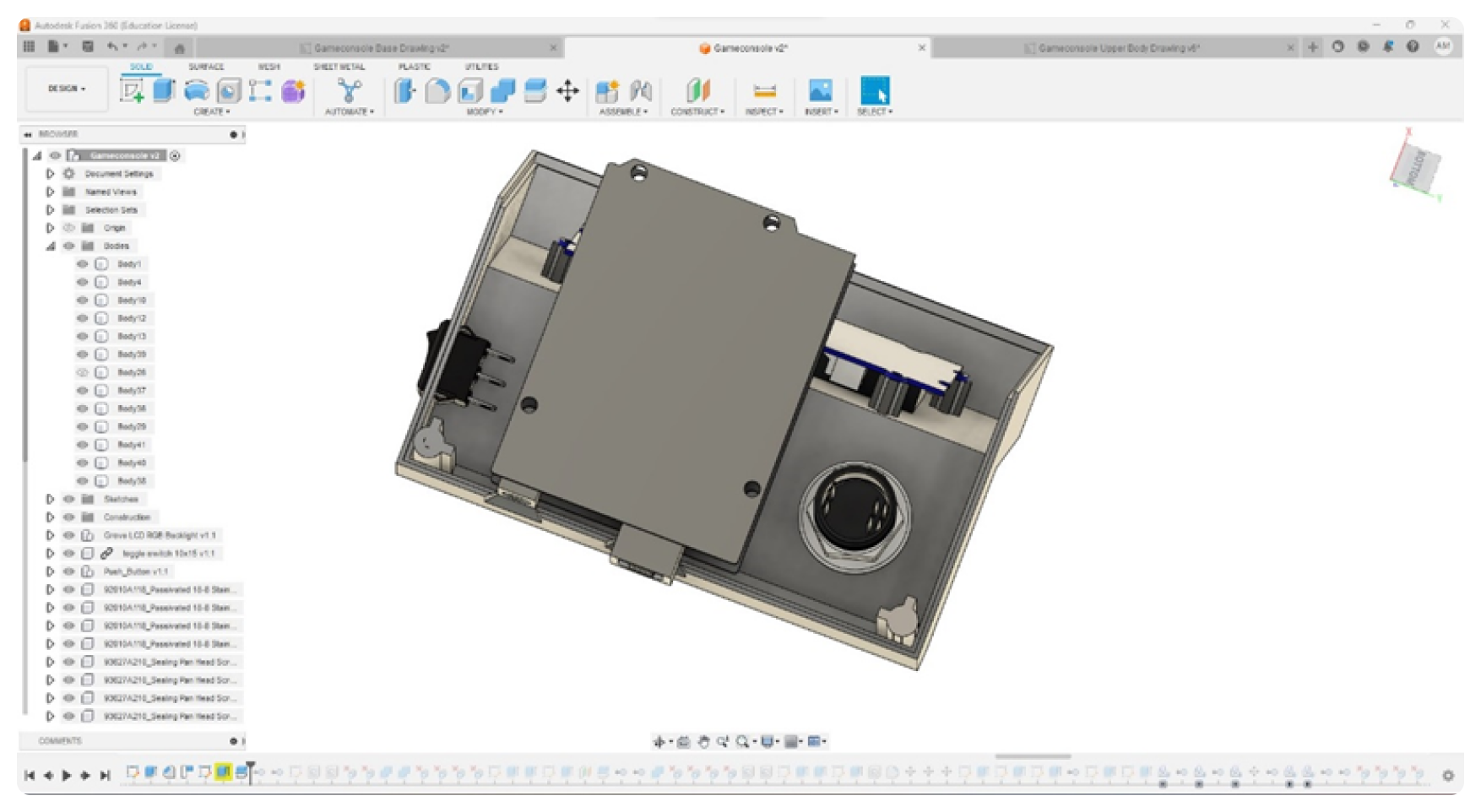
First, I gathered all the necessary components and placed them in the design space. I then duplicated the Arduino and copied the shield dimensions onto it. I made sure to include the LED and clear out any extra unwanted surfaces. Next, I placed the LCD screen and button by downloading the standard CAD and importing into fusion. I positioned them approximately to clear the enclosure around them.

I start to create a rough outline of the side profile based on the sketch and measured the distance of the Arduino from the base and walls, as well as for the rest of the components. I extruded that plane to give it a 3D depth and removed any extra surfaces created by the application. I replaced the components and centred them internally to make cut-outs for them to fit the screen, button, and other parts. Using the reference of the standard CAD models I managed to get approximate positions for the cut-outs. Based on where the LED lights were inside, I extrude-cut that on the projected surface because we need to see the LED’s.
For the diffuser caps, I designed their shape and depth so that they could hold onto the LED inside. I duplicated the diffuser caps to create the same for the other two holes. I then created a side cut-out for the power button and combined all surfaces, making sure that the entire piece was still one piece. I extrude cut holes for the power socket and the USB socket for the Arduino and gave them a chamfer for easy access and visible because at times when the wall thickness is state and its close to the edge you don’t seethe components or ports inside. I didn’t use fillet here because the visibility provided by a fillet is lesser than a chamfer.
I divided the entire piece into two separate parts so that I can start building it internally. For the first trial, I thought what if the parting line was going from below and going across. I tried to place the power between the slit but then changed it because there would be some issues with the locking mechanism for the switch to be affixed. So that’s why I shifted the slit a little lower to the power button. I then split the board through using the plane and modified it to match the internal power socket.
An advantage of Fusion360 is that it provides us with a timeline which we can go back to and make changes and the changes are reflected in the later processes of the timeline as well. So, I try to make the lift and the lip is an important component to join the two parts together. If there is a lip, it is easier to align the parts and they sit properly with each other. I decided to change the parting line from a straight part to two L-shaped surfaces that can combine together. This made the mounting of the screen easier because the screen could be mounted onto one part easily, and that part could be combined with the lower half. I split it into two parts to make the assembly of the entire product easy.
To create the lip, I made it in two parts. First, I extruded the lip of the lower half, which was easy because I could just exclude one mm from the two mm wall thickness. However, to make it at an angle, I had to first extrude it parallel to the surface and then extrude it long enough to meet the slanted plane. Then, I made a plane parallel to the slanted plane by 2mm and split that additional part to give me the desired lip. I combined all three parts to make it uniform and look like one part. I did the same thing to make the lip for the top part.
To make the ribs and bosses for the screen and the Arduino, I projected the holes onto the surface and then extruded them. I made one and then duplicated it based on the number of holes and deleted any extra identity surfaces that were being created. I made ribs and bosses for the top part so that I could combine both those two pieces together. I decided to give it four bolting points and four more bolting points for the four corners.
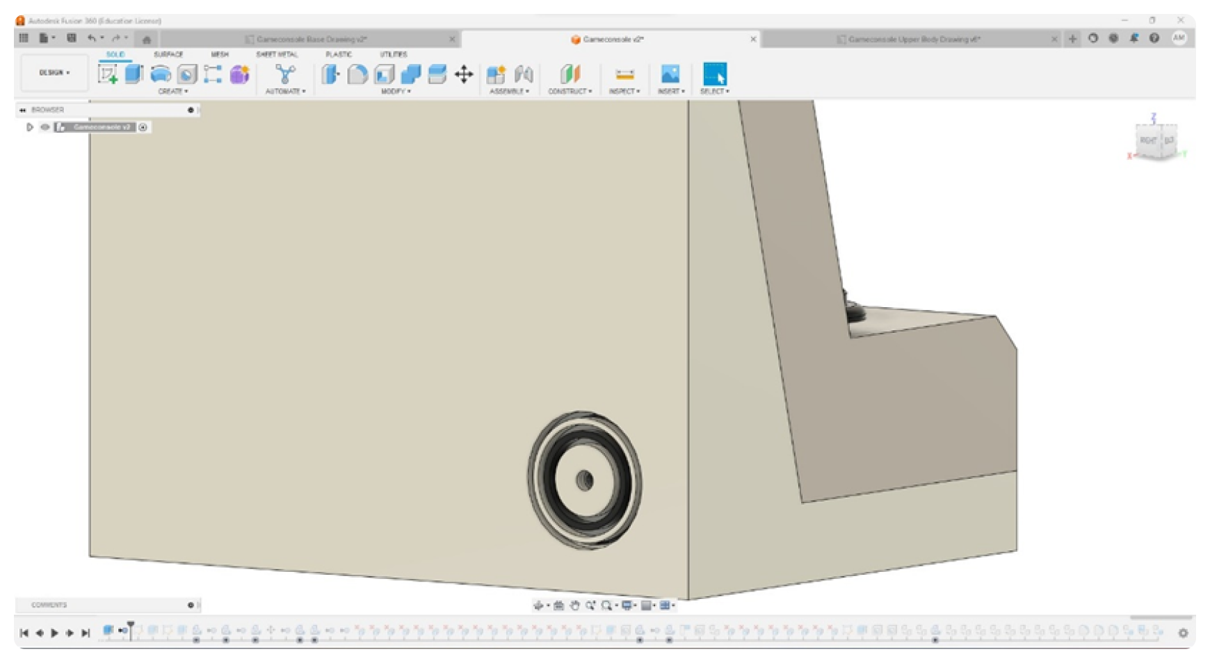
I also made a holder and cut-out for the speaker and other components. First, I offset the plane to create the sketch on the plane, followed by creating a circle for the orifice of the beeper. After which I offset this circle concentrically three times of variable lengths and extruded them towards the body creating the cut-out for the speaker grill. Then I added colour, put in the bolts, and combined all the bodies together to create the final product. I made a cut-out for the screen, and for the switch, I made the cut-out as per that component.

I made the mounting wheel for the Arduino by projecting the board onto the base and made the ribs and bosses again. Most of it was projection, extrude-cut and extrude. I even made a lip for the bulb so that it fits properly and holds it in place. I did this to give a bit of small skirting and to make the fitting better. At last, I added fillets to all the edges.
After having completed the model I sliced it in Ultimaker Cura and 3D printed a miniature version of the model as a test.


